Monday, 14 May 2012

Basic Vlans and Trunks Part 4
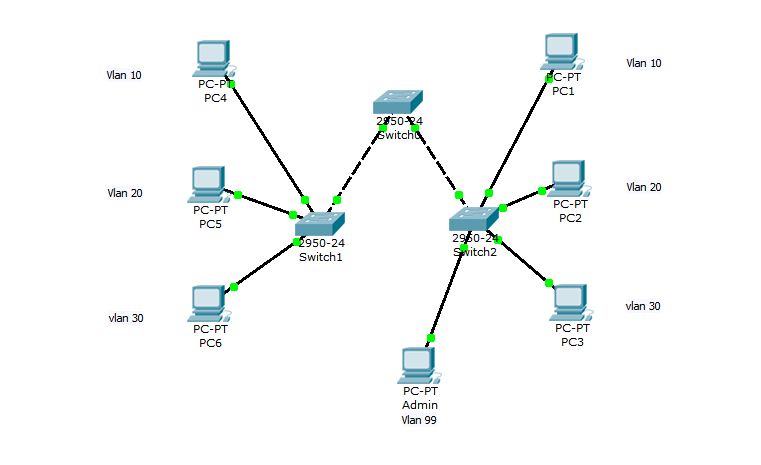

 Basic Vlans and Trunks Part 4


1.      Take 3 Switches.
2.      Connect 3 switches through cross over.
3.     Configure the Hostname as well as the Vlans.
        Switch>
                   Switch>enable
                   Switch#hostname
                  Translating "hostname"...domain server (255.255.255.255)
                  % Unknown command or computer name, or unable to find computer address

                  Switch#config t
                  Enter configuration commands, one per line.  End with CNTL/Z.
                  Switch(config)#hostname CCNA
                  CCNA(config)#vlan 99
                   CCNA(config-vlan)#name Admin
                   CCNA(config-vlan)#exit
                  CCNA(config)#vlan 10
                  CCNA(config-vlan)#name MLAB
                  CCNA(config-vlan)#exit
                   CCNA(config)#vlan 20
                   CCNA(config-vlan)#name ALAB
                   CCNA(config-vlan)#exit
                   CCNA(config)#vlan 30
                   CCNA(config-vlan)#name ELAB
                   CCNA(config-vlan)#exit
                   CCNA(config)#exit
                   CCNA# copy running-config startup-config
                   Destination filename [startup-config]?
                   Building configuration...
                   [OK]
                   CCNA#

4.      Same configuration on another switches.
5.      Take 7 systems and rename as the following figure.
6.       Using the Config tab in Packet Tracer, configure the IP address, mask, and default gateway on each host. 
 PC – 192.168.10.100 255.255.255.0
 PC – 192.168.10.101 255.255.255.0

PC – 192.168.20.100 255.255.255.0
PC – 192.168.20.101 255.255.255.0

PC – 192.168.30.100 255.255.255.0
PC – 192.168.30.101 255.255.255.0

Admin System 192.168.99.100 255.255.255.0

7.      Configure the Vlans on switch0(CCNA). 
               CCNA2#config t
                Enter configuration commands, one per line.  End with CNTL/Z.
                CCNA2(config)#int range fa0/6-10
                CCNA2(config-if-range)#switchport mode access
                 CCNA2(config-if-range)#switchport access vlan 10
                 CCNA2(config-if-range)#exit
                 CCNA2(config)#int range fa0/11-17
                 CCNA2(config-if-range)#switchport mode access
                 CCNA2(config-if-range)#switchport access vlan 20
                 CCNA2(config-if-range)#exit
                 CCNA2(config)#int range fa0/18-23
                 CCNA2(config-if-range)#switchport mode access
                 CCNA2(config-if-range)#switchport access vlan 30
                 CCNA2(config-if-range)#exit
                 CCNA2(config)#int fa0/24
                  CCNA2(config-if)#switchport mode access
                  CCNA2(config-if)#switchport access vlan 99
                   CCNA2(config-if)#exit
                   CCNA2(config)#exit
8.      Same configuration on another switches    
9.      Configure the trunk
Switch CCNA
                  CCNA>enable
                   CCNA#config t
                   Enter configuration commands, one per line.  End with CNTL/Z.
                    CCNA(config)#int range fa0/1-2
                     CCNA(config-if-range)#switchport mode trunk

                  %LINEPROTO-5-UPDOWN: Line protocol on Interface FastEthernet0/1, changed state to 
                   down

                 %LINEPROTO-5-UPDOWN: Line protocol on Interface FastEthernet0/1, changed state to up


                  %LINEPROTO-5-UPDOWN: Line protocol on Interface FastEthernet0/2, changed state to 
                    down

                 %LINEPROTO-5-UPDOWN: Line protocol on Interface FastEthernet0/2, changed state to up

                CCNA(config-if-range)#switchport trunk native vlan 99
              CCNA(config-if-range)#exit
            
                   CCNA(config-if)#exit
                   CCNA(config)#exit
              Switch CCNA1
                     CCNA1#config t
                    Enter configuration commands, one per line.  End with CNTL/Z.
                     CCNA1(config)#int fa0/1
                     CCNA1(config-if)#switchport mode trunk
                      CCNA1(config-if)#switchport mode
                      %CDP-4-NATIVE_VLAN_MISMATCH: Native VLAN mismatch discovered on 
                       FastEthernet0/1                        
                      (1), with CCNA FastEthernet0/1 (99).

                        % Incomplete command.
                       CCNA1(config-if)#switchport trunk native vlan 99
                       CCNA1(config-if)#exit
                       CCNA1(config)#exit
                    Switch CCNA2
                     CCNA2#config t
                      Enter configuration commands, one per line.  End with CNTL/Z.
                     CCNA2(config)#int fa0/1
                     CCNA2(config-if)#switchport mode trunk
                      CCNA2(config-if)#switchport mode
                      %CDP-4-NATIVE_VLAN_MISMATCH: Native VLAN mismatch discovered on     
                       FastEthernet0/1                        
                      (1), with CCNA FastEthernet0/1 (99).

                        % Incomplete command.
                       CCNA2(config-if)#switchport trunk native vlan 99
                       CCNA2(config-if)#exit
                       CCNA2(config)#exit

                      Now try to ping from PC 192.168.10.100 to 192.168.10.101.

                               If is there any mistakes and for any clarification please mail to  
                                                    ccnalab06@gmail.com


Wednesday, 9 May 2012

Basic Vlans and Trunks Part 3


 Basic Vlans and Trunks Part 3

1.      Take 2 Switches.
2.      Connect 2 switches through cross over cable from Fastethernet 0/1 to Fastethernet 0/1.
3.     Configure the Hostname as well as the management LAN settings.
Switch>Enable
Switch#Config t
Switch(config)#hostname CCNA_1
CCNA_1(config)#interface VLAN 1
CCNA_1(config-if)#ip address 192.168.1.1 255.255.255.0
CCNA_1(config-if)#no shut

CCNA_1(config)#
ip default-gateway 192.168.1.254
Switch>Enable
Switch#Config t
Switch(config)#hostname CCNA_2
CCNA_2(config)#interface VLAN 1
CCNA_2(config-if)#ip address 192.168.1.2 255.255.255.0
CCNA_2(config-if)#no shut

CCNA
_2(config)#ip default-gateway 192.168.1.254.
4.      Take 6 systems and rename as M1,M2,A1,A2,E1 and E2 as in the figure.
5.       Using the Config tab in Packet Tracer, configure the IP address, mask, and default gateway on each host. 
A1 – 192.168.10.1 255.255.255.0 with a default gateway of 192.168.10.254
A2 – 192.168.10.2 255.255.255.0 with a default gateway of 192.168.10.254

M1 – 192.168.20.1 255.255.255.0 with a default gateway of 192.168.20.254
M2 – 192.168.20.2 255.255.255.0 with a default gateway of 192.168.20.254

E1 – 192.168.30.1 255.255.255.0 with a default gateway of 192.168.30.254
E2 – 192.168.30.2 255.255.255.0 with a default gateway of 192.168.30.254

6.      Configure the Vlans on switch0(CCNA_1). 
       CCNA_1#config t
   CCNA_1(config)#vlan 10
   CCNA_1(config-vlan)#name M1
   CCNA_1(config-nlan)#exit
   CCNA_1(config)#
   CCNA_1(config)#vlan 20
   CCNA_1(config-vlan)#name A1
   CCNA_1(config-nlan)#exit
   CCNA_1(config)#
   CCNA_1(config)#vlan 30
   CCNA_1(config-vlan)#name E1
   CCNA_1(config-nlan)#exit
   CCNA_1(config)#exit
   CCNA_1#
7.      Configure the Vlans on switch1(CCNA_2). 
   CCNA_2#config t
   CCNA_2(config)#vlan 10
   CCNA_2(config-vlan)#name M1
   CCNA_2(config-nlan)#exit
   CCNA_2(config)#
   CCNA_2(config)#vlan 20
   CCNA_2(config-vlan)#name A1
   CCNA_2(config-nlan)#exit
   CCNA_2(config)#
   CCNA_2(config)#vlan 30
   CCNA_2(config-vlan)#name E1
   CCNA_2(config-nlan)#exit
   CCNA_2(config)#exit
   CCNA_2#
8.      Assign ports to VLAN
     CCNA_1#configure terminal
      CCNA_1(config)#interface fastethernet 0/2
      CCNA_1(config-if)#switchport mode access
CCNA_1(config-if)#switchport access vlan 10
 
CCNA_1#configure terminal
      CCNA_1(config)#interface fastethernet 0/3
CCNA_1(config-if)#switchport mode access
CCNA_1(config-if)#switchport access vlan 20

CCNA_1#configure terminal
      CCNA_1(config)#interface fastethernet 0/4
CCNA_1(config-if)#switchport mode access
CCNA_1(config-if)#switchport access vlan 30

          Another switch CCNA_2
           CCNA_2#configure terminal
      CCNA_2(config)#interface fastethernet 0/2
CCNA_2(config-if)#switchport mode access
CCNA_2(config-if)#switchport access vlan 10

CCNA_2#configure terminal
      CCNA_2(config)#interface fastethernet 0/3
CCNA_2(config-if)#switchport mode access
CCNA_2(config-if)#switchport access vlan 20

CCNA_2#configure terminal
      CCNA_2(config)#interface fastethernet 0/4
CCNA_2(config-if)#switchport mode access
CCNA_2(config-if)#switchport access vlan 30
 
9.      Configure the trunk
             CCNA_1(config)#interface fastethernet 0/1
                  CCNA_1(config-if)#switchport mode trunk
                  CCNA_1(config-if)#end
                  CCNA_2(config)#interface fastethernet 0/1  
                   CCNA_2(config)#switchport mode trunk
                  CCNA_2(config)#end

10.   Test the VLANs and the Trunk

                  Ping from the E1 host to the E2 host The ping should be successful.


     If is there any mistakes and for any clarification please mail to ccnalab06@gmail.com (zerosix)


Tuesday, 8 May 2012

Basic Vlans and Trunks Part 2


 Basic Vlans and Trunks Part 2

1.      Take 12 systems.                                 
2.      Change top three systems name and IP Address as
 (Morning Lab F 192.168.1.97    Afternoon Lab F 192.168.1.98   Evening Lab F 192.168.1.99)
3.      Change left three systems name and IP Address as
 (Morning Lab1  192.168.1.27    Morning Lab2  192.168.1.28   Morning Lab3  192.168.1.29)
4.      Change Down three systems name and IP Address as
 (Afternoon Lab1  192.168.1.37    Afternoon Lab2  192.168.1.38   Afternoon Lab3  192.168.1.39)
5.      Change left three systems name and IP Address as
 (Evening Lab1  192.168.1.47    Evening Lab2  192.168.1.48   Evening Lab3  192.168.1.49)
6.      Take  One switch2960 and configure as shown below.
       Single click on switch and select CLI (IOS command line interface)
       Switch>
       Switch>enable
       Switch#config t
             Enter configuration commands, one per line.  End with CNTL/Z.
      Switch(config)#hostname CCNA
      CCNA(config)#vlan 10
      CCNA(config-vlan)#name LabF
      CCNA(config-vlan)# vlan 20
     CCNA(config-vlan)#name MorningLab
     CCNA(config-vlan)# vlan 30
     CCNA(config-vlan)#name AfternoonLab
     CCNA(config-vlan)# vlan 40
     CCNA(config-vlan)#name EveningLab
     CCNA(config-vlan)#exit
     CCNA(config)#exit
     CCNA#
       Now we will check vlans
      CCNA# show  vlan
        Now we will access switrchport to vlan
     CCNA#
     CCNA# config t
             Enter configuration commands, one per line.  End with CNTL/Z.
     CCNA(config)#interface fastethernet 0/1
     CCNA(config-if)#switchport mode access
     CCNA(config-if)#switchport access vlan 20
     CCNA(config-if)#exit
      CCNA(config)#interface fastethernet 0/2
     CCNA(config-if)#switchport mode access
     CCNA(config-if)#switchport access vlan 30
     CCNA(config-if)#exit
      CCNA(config)#interface fastethernet 0/3
     CCNA(config-if)#switchport mode access
     CCNA(config-if)#switchport access vlan 40
     CCNA(config-if)#exit
      CCNA(config)#interface fastethernet 0/4
     CCNA(config-if)#switchport mode access
     CCNA(config-if)#switchport access vlan 20
     CCNA(config-if)#exit
      CCNA(config)#interface fastethernet 0/5
     CCNA(config-if)#switchport mode access
     CCNA(config-if)#switchport access vlan 20
      CCNA(config-if)#exit
      CCNA(config)#interface fastethernet 0/6
     CCNA(config-if)#switchport mode access
     CCNA(config-if)#switchport access vlan 20
      CCNA(config-if)#exit
      CCNA(config)#interface fastethernet 0/7
     CCNA(config-if)#switchport mode access
     CCNA(config-if)#switchport access vlan 30
     CCNA(config-if)#exit
      CCNA(config)#interface fastethernet 0/8
     CCNA(config-if)#switchport mode access
     CCNA(config-if)#switchport access vlan 30
     CCNA(config-if)#exit
      CCNA(config)#interface fastethernet 0/9
     CCNA(config-if)#switchport mode access
     CCNA(config-if)#switchport access vlan 30
     CCNA(config-if)#exit
      CCNA(config)#interface fastethernet 0/10
     CCNA(config-if)#switchport mode access
     CCNA(config-if)#switchport access vlan 40
     CCNA(config-if)#exit
      CCNA(config)#interface fastethernet 0/11
     CCNA(config-if)#switchport mode access
     CCNA(config-if)#switchport access vlan 40
     CCNA(config-if)#exit
      CCNA(config)#interface fastethernet 0/12
     CCNA(config-if)#switchport mode access
     CCNA(config-if)#switchport access vlan 40
     CCNA(config-if)#end
     CCNA#show vlan
       

  Now try to ping from one Morning Lab F(192.168.1.97) to Morning Lab 1(192.168.1.27)
   It will replay.
  Now try to ping from one Morning Lab 1(192.168.1.97) to Morning Lab 3(192.168.1.29)
   It will replay.
 Now try to ping from one Morning Lab 1(192.168.1.97) to Afternoon Lab 3(192.168.1.39)
   It will Show request timeout.
Try it from Afternoon and Evening Labs.
           If is there any mistakes and for any clarification mail to ccnalab06@gmail.com  .  (ZeroSix)


Saturday, 5 May 2012

Basic Vlans and Trunks Part 1


                  Basic Vlans and Trunks Part 1
1.      Take two systems and one switch. (Change system name as LAB and another one as Student)
3.      Connect two systems to switch through Straight cable.
4.      Connect (System) LAB to switch port 5.
5.      Connect another (system) Student to switch port 6.
6.      Configure both system IP as (192.168.1.100    192.168.1.101).
7.      Now try to ping from one system to another.
8.      Now we need to configure vlans.
9.      Single click on switch and select CLI (IOS command line interface).
        Switch>
       Switch >enable
       Switch#config terminal
       Switch (config) # vlan 50
       Switch (config –vlan)#name student    ( Now vlan 50 has changed to vlan Student)
       Switch (config –vlan)#vlan 99
       Switch (config –vlan)#name LAB           (Now vlan 99 has changed to vlan LAB)
       Switch (config –vlan)#exit
       Switch (config)#exit
       Switch#        (Vlans are modified)
       Change switch fastethernet ports to vlans according to our systems.
       Switch# configure terminal
       Switch (config) # interface fastEthernet 0/5
       Switch (config-if)# switchport mode access
       Switch (config-if)# switchport access vlan 50
       Switch (config-if)# exit
       Switch# configure terminal
       Switch (config) # interface fastEthernet 0/6
       Switch (config-if)# switchport mode access
       Switch (config-if)# switchport access vlan 99.
       Switch (config-if)# exit
       Switch#
10.   Now try to ping from one computer to another computer, it will show Request time out
But both systems can access internet. Both are in different vlans in same switch.

If any clarification please mail to ccnalab06@gmail.com   (Zerosix)


Friday, 4 May 2012

Types of VLAN


There are different types of VLANs. The type of network traffic they carry defines a particular type of VLAN and others derive their
names due to the type or a specific function the VLAN performs. The following describes common VLAN:
Default VLAN
At the initial boot up of the switch, All switch ports become a member of the default VLAN, which makes them all part of the same broadcast domain. This allows any network device connected to any of the switch port to communicate with other devices on other switch ports.
On Cisco switches the default VLAN is VLAN 1. VLAN 1 has all the features of any VLAN, except that you cannot rename or delete it.
Data VLAN
A data VLAN that can also be referred to as user VLAN. This is configured to carry only user-generated traffic. The importance of separating user data from other type of VLAN is proper switch management and control.
Native VLAN
A native VLAN is assigned to an 802.1Q trunk port. An 802.1Q trunk port supports traffic coming from many VLANs as well as traffic that do not come from a VLAN. The 802.1Q trunk port places untagged traffic (traffic that does not come from a VLAN) on the native VLAN. In summary, the native VLAN observes and identifies traffic coming from each end of a trunk link.
Management VLAN
A management VLAN is any VLAN you configure to access the management capabilities of a switch. Your configured management VLAN is to be assign with an IP address and subnet mask. Any of a switch VLAN could be configured as the management VLAN if you has not configured or define a unique VLAN to serve as the management VLAN. In some cases, a network administrator proactively defines VLAN 1 as the management VLAN; this enables a loophole for an unauthorized connection to a switch.
Voice VLAN
Voice VLAN is configured to carry voice traffic. Voice VLANs are mostly given transmission priority over other types of network traffic. Communication over the network is not complete without phone calls. More calls are made over the network than other forms of s message transmission. Sending emails and text messages are also forms of inter-relations but listening to a real voice provides legitimacy and assurance.
It is considered among network administrators to design a network that support VoIP with an assured bandwidth to ensure voice quality, and capability to be routed around congested areas on the network with minimal delays (150-180 milliseconds).

In next post we will see each VLAN in practicals.

Thursday, 26 April 2012

Basic Router Connecting LAN Interfaces


Basic Connecting Router LAN Interfaces.
Step By Step
1.       Take one router 2620xm
2.       Take one switch
3.       Take 2 PC
4.       Use straight-through cables for all connections.
5.       Configure router as shown below.
Router>en
Router#config t
Router(config)#int fa0/0
Router(config-if)#ip address 192.168.1.1 255.255.255.0
Router(config-if)#no shutdown
6.     PC0 IP Address 192.168.1.1  Subnet Mask 255.255.255.0  Default Gateway 192.168.1.1
7.     PC1 IP Address 192.168.1.3  Subnet Mask 255.255.255.0  Default Gateway 192.168.1.1
8.     Ping from PC0 to PC1.

Tuesday, 24 April 2012

Small network between two hubs and one switch.

Step by step
1.       Take seven systems and 2 hubs 1 switch.
2.       Add four systems to one hub and remaining three to another hub as shown in above image
3.       Add two hubs to one switch.
4.       Add IP address to system Ex ( 192.168.1.0  to 192.168.1.7)
5.       Now ping from PC1 to PC6 and check.

Note:- In this tutorial we are just configuring network. We are not in depth. In next coming class we will
         See how to configure switches, Routers in making a perfect Network. We will move step by step.